| 規格介紹: |
 |
 |
|
|
HD-1000DMCW / HD-2000DMCW
Dual Mode High Definition Digital Modulator
Specifications |
 |
HD-2000DMCW |
 |
HD-1000DMCW |
|
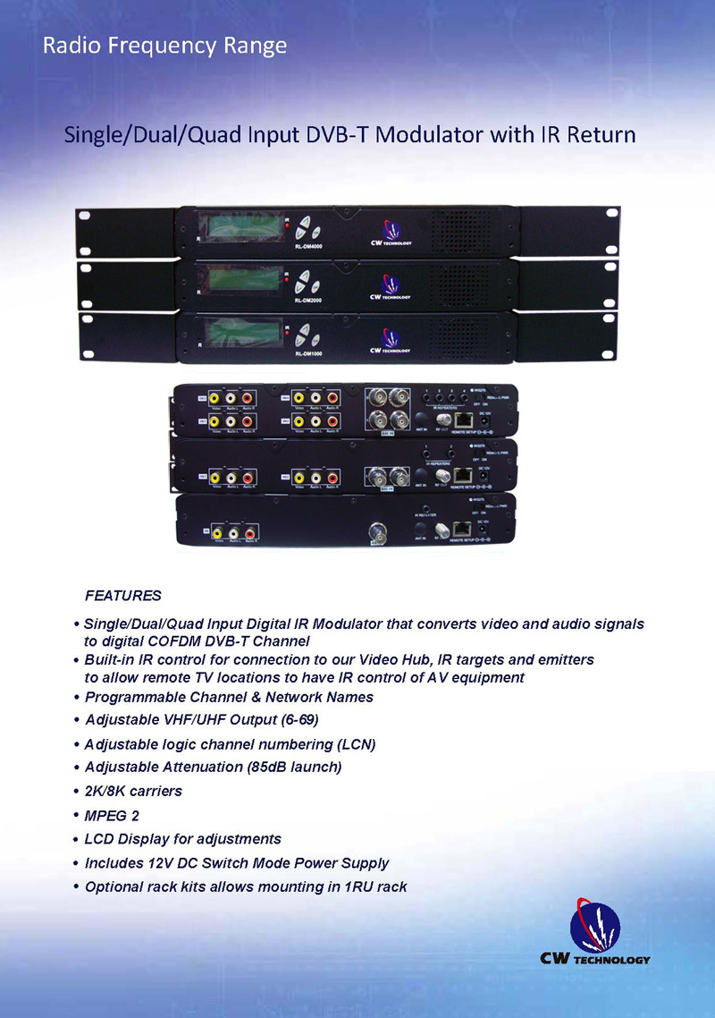
ZyCast Technology's HD-1000DMCW / HD-2000DMCW Modulators convert Digital Video Broadcasting (DVB) high definition video and audio signals to COFDM. The Dual Mode HD-1000DMCW, HD-2000DMCW Modulators provide respectively single, dual inputs. All units feature programmable channel and network names. Adjustable VHF/UHF output (Standard, IRD, HRC frequency channel), adjustable logic channel numbering (LCN) and adjustable attenuation are standard features. The unit's front-mounted LCD display and controls allow for easy configuration and adjustments.
The HD-1000DMCW, HD-2000DMCW Modulators are perfect for multi-video distribution solutions in the commercial and institutional market (hotels, motels, sports bars, restaurants, hospitals, casinos, business and university campuses, digital signage, etc.) as well as home entertainment systems.
Features
☼ HDMI, Component (AV), Composite (YCBCR), ASI inputs with auto detection
☼ Dual Mode H.264 AVC (MPEG4) / MPEG2 selectable
☼ Video resolution :1080i /720p/576i/480p/480i for all, 1080p for (AVC)MPEG-4
☼ Perfect, clean, and clear picture on high motion video, sports, text crawls/rolls, etc.
☼ Front Panel LCD for easy setup
☼ Cool & silent operation (internal fan cooled)
☼ Rack Mountable for easy installation
☼ Easily retrofit any existing installation by replacing the Analog Modulator with ZyCast’s Digital Modulator |
| Technical Specifications |
| INPUT輸入 |
HD-1000DMCW |
HD-2000DMCW |
| Input Connectors 輸入接頭 |
HDMI input (Video + Audio) |
HDMI input (Video + Audio) |
| Y C b Cr component input (Video) |
Y C b Cr component input (Video) |
| AV Composite input (Video) |
AV Composite input (Video) |
| L / R_ channel Audio input (Audio) |
L / R_ channel Audio input (Audio) |
| Coaxial SPDIF input (Digital Audio) |
Coaxial SPDIF input (Digital Audio) |
| Optical SPDIF input (Digital Audio) |
Optical SPDIF input (Digital Audio) |
| ASI input (serial TS) |
ASI input (serial TS) |
| Video Input 影像輸入 |
HDMI/Component/Composite |
HDMI/Component/Composite |
| Video Input Level影像輸入電平 |
0.7 – 1.4V(peak-to peak) |
0.7 – 1.4V(peak-to-peak) |
| Video Mode 影像模式 |
PAL / NTSC |
PAL / NTSC |
| Audio input 音頻輸入 |
Stereo |
Stereo |
| Audio Input Level音頻輸入電平 |
0.4 – 4.8V (p-to-p) |
0.4 – 4.8V (p-to-p) |
| Input Impedance 輸入阻抗 |
75Ω |
75Ω |
| OUTPUT輸出 |
|
|
| Frequency Range |
Local country available |
Local country available |
| Output Level 輸入電平 |
85 dBμV |
85 dBμV |
| Output Impedance輸出阻抗 |
75 ohm |
75 ohm |
| Channel Bandwidth頻道頻寬 |
6,7,8 MHz |
6,7,8 MHz |
| Channel Level Adjustment |
20 dB typ. |
20 dB typ. |
| MER 調製誤差率 |
32 dB typ. |
32 dB typ. |
| Video Resolution影像解析度 |
1080i/720p/576i/480p/480i for all
1080p for AVC(MPEG-4) |
1080i/720p/576i/480p/480i for all
1080p for AVC(MPEG-4) |
| Video Compression影像壓縮 |
H.264 AVC(MPEG-4) / MPEG2 MP@ML |
H.264 AVC(MPEG-4) / MPEG2 MP@ML |
| Audio Compression音頻壓縮 |
MPEG1 Layer II/AAC
AC-3 Pass through |
MPEG1 Layer II/AAC
AC-3 Pass through |
| LCN |
Yes |
Yes |
Carrier (OFDM Mode)
正交分頻多工技術模式 |
2K/8K |
2K/8K |
| Guard Intervals保護區間 |
1/32 |
1/32 |
| Code Rate (FEC)正向錯誤更正 |
7/8 |
7/8 |
| Constellations解調方式 |
64 QAM |
64 QAM |
| GENERAL |
|
|
| Power Supply電源供應 |
12 VDC 3 Amp. |
12 VDC 3 Amp. |
| Consumption耗電 |
1250 mA |
1650 mA |
| Languages語言 |
English |
English |
| Dimensions尺寸 |
482.7mm x 240mm x 44.4mm
(19" x9.45" x 1.75") |
482.7mm x 240mm x 44.4mm
(19" x9.45" x 1.75") |
| Weight重量 |
3.1 KGS |
3.1 KGS |
|
*Specifications subject to change without prior notice |
| ALL rights reserved |
|
|
Setting Options |
| Settings |
Default Settings |
Optional Settings |
| HD-1000DMCW |
HD-2000DMCW |
| OUTPUT CHANNEL輸出頻道 |
21 UHF / S31 UHF |
21 UHF / S31 UHF |
6-69 / E2 – E69 |
| FEC ( forward error correction) 正向錯誤更正 |
7/8 |
7/8 |
7/8 |
| GUARD INTERVAL 保護區間 |
1/32 |
1/32 |
1/32 |
| ATTENUATION衰減 |
0 |
0 |
0~20dB |
| CONSTELLATION解調方式 |
64QAM |
64QAM |
64QAM |
| OFDM MODE正交分頻多工技術模式 |
8K |
8K |
2K |
| RF OUTPUT輸出 |
Normal |
Normal |
Inverted, C.W. |
| VIDEO INPUT影像輸入 |
AUTO |
AUTO |
HDMI ASI COMPOSITE COMPONENT |
| BRIGHTNESS亮度 |
128 |
128 |
0~255 |
| CONTRAST對比 |
128 |
128 |
0~255 |
| SATURATION飽和度 |
128 |
128 |
0~255 |
| SHARPNESS銳利度 |
RESERVE |
RESERVE |
RESERVE |
| HUE色度 |
128 |
128 |
0~255 |
| DEVICE ADDRESS(設備位址) |
1 |
1 |
1-32 Adjustable |
| CELL ID |
0 |
0 |
0-65535 Adjustable |
| STREM ID |
1000 |
1000 |
0-65535 Adjustable |
| NETWORK ID (網路識別碼) |
100 |
100 |
0-65535 Adjustable |
| ORG NETWORK ID |
10 |
10 |
0-65535 Adjustable |
| NETWORK NAME網路名稱 |
RL- NETWORK |
RL- NETWORK |
Adjustable |
| PROGRAM NUMBER |
1001 |
1001 |
Adjustable |
| CHANNEL NAME頻道名稱 |
CHANNEL-1 |
CHANNEL-1 |
Adjustable |
| LCN電視頻道號碼 |
101 |
101 |
Adjustable |
| ASPECT RATIO(長寬比) |
16:9 |
16:9 |
4:3( FOR MPEG-2) |
| LCN MODE |
APN |
APN |
EACEM, ITC, NORDIG |
| VIDEO OUPUT影像輸出 |
MPEG-2 |
MPEG-2 |
AVC(MPWG-4) |
| HDCP |
ENABLE(啟用) |
ENABLE(啟用) |
DISABLE (禁用) |
| AUDIO INPUT聲音輸入 |
AUTO |
AUTO |
ANALOG COAXIAL
OPTICAL HDMI |
| AUDIO OUPUT聲音輸出 |
AC3 |
AC3 |
MP2.AAC |
|
Ordering information: |
HD-1000DMCW -- Dual Mode High Definition Single Channel Digital Modulator |
| HD-2000DMCW -- Dual Mode High Definition Dual Channel Digital Modulator |
All rights reserved |
|
|
|
|
HDIP-800 / HDIP-900
High Definition IP Streamer
Specifications |
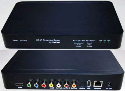 |
烝偉科技's HDIP-800 / HDIP-900 HD IP Streamer allows the user to stream any one audio/video source over a IP Network to up to any 16 Smart HD TV's or connected computers within the IP Network. The IP Streamer accepts a HDMI, Component, or Composite video input and the unit is designed to deliver a rich HD/SD Streaming experience for it's users deploying MPEG-2 or MPEG-4 standards.
Combine any sources and stream them over the network for multiple sources. The compact design saves space and is easily controlled via a GUI for rapid deployment.
This HD Streamer enables high-definition streaming up to 1080p HD, making content even more fascinating and interesting. The unit is MPEG2 or MPEG4 switchable and supports UDP/RTP Streaming.
The HDIP-800 / HDIP-900 HD IP Streaming Server is perfect for HD Classrooms, Pro AV Systems, Corporate Board Rooms, CCTV IP Streaming, and HD distribution over IP networks. |
|
| Features |
| ☼ HDMI, Component, Composite inputs with auto detection |
| ☼ Dual Mode H.264 AVC / MPEG-2 selectable |
| ☼ Video resolution: Up to 1080p |
| ☼ Audio format : MPEG1-Layer2(MP2), AAC |
| |
AC-3 passthrough for HDIP-800 |
| |
AC-3 for HDIP-900 |
| ☼ Easy installation and use |
| ☼ GUI for setup and control |
| ☼ GigE output port |
|
| Technical Specifications |
| Interfaces |
Ethernet (output) |
1Gbps, RJ-45 |
| |
USB (optional) |
USB 2.0 |
| |
Video Input |
HDMI, YPbPr, CVBS |
| |
Audio Input |
Analog, Coaxial, Optical |
| Encoding |
Video Format |
MPEG-2, AVC |
| |
Audio Format |
MPEG-1 Layer2(MP2), AAC, AC-3
passthrough for HDIP-800 AC-3
for HDIP-900 |
| |
Resolution |
480i, 480p, 576i, 576p, 720p, 1080i, 1080p |
| |
Video bitrate |
MPEG-2: 10~20Mbps AVC: 2~10Mbps |
| |
Audio bitrate |
MP2: 128, 256, 384Kbps AAC, AC-3: 128, 256Kbps |
| |
Streaming Protocols |
HTTP Server (DLNA) UDP/RTP multicast UDP/RTP unicast TCP unicast |
| |
Digital Living Network
Alliance (DLNA) |
MediaServer 1.5 |
| |
Closed Caption |
Yes |
| |
Power Supply |
12VDC 1.5Amp. |
| |
Consumption |
500mA |
| |
Dimension |
236mm x 155mm x 35mm |
| |
Weight |
940g |
| *Specifications subject to change without prior notice |
| Ordering information: |
| HDIP-800 – High Definition Digital IP Streamer, non-AC3 |
| HDIP-900 – High Definition Digital IP Streamer, AC3 |
| All rights reserved |
|
|
|
INSTALLATION &CONFIGURATIONMANUAL
HD-1000DM / HD-2000DM / HD4000DM (
DVB - T HD Series)
Single / Dual / Quad Input QAM
Encoders / Modulators |
 |
|
SAFETY PRECAUTIONS
|
 |
The presence of this symbol is to alert the installer and user to the presence of uninsulated dangerous voltages within the product’s enclosure that may be of sufficient magnitude to produce a risk of electric shock.
TO REDUCE THE RISK OF FIRE OR ELECTRIC SHOCK, DO NOT
EXPOSE THIS DEVICE TO RAIN OR MOISTURE. DO NOT OPEN THE UNIT.REFER SERVICING TO QUALIFIED PERSONNEL ONLY. |
|
| ※ |
DO NOT apply power to the unit until all connections have been made, all components have been |
| |
installed and all wiring has been properly terminated. |
| ※ |
DO NOT terminae, change or uninstall any wiring without first disconnecting the unit’s power adapter |
| |
from the device. |
| ※ |
This device is supplied with the appropriately rated 12VDC power supply with the center pin positive.
|
| |
The use of any other power supply could cause damage and invalidate the manufacturer’s warranty. |
| ※ |
DO NOT connect the power cord to the device if the power cord is damaged. |
| ※ |
DO NOT cut the power cord. |
| ※ |
DO NOT plug the power cord into an AC outlet until all cables and connections to the device have been
|
| |
properly connected. |
| ※ |
The device should be installed in an environment consistent with its operating temperature
|
| |
specifications. Placement next to heating devices and ducts is to be avoided as doing so may cause
|
| |
damage. The device should not be placed in areas of high humidity. |
| ※ |
DO NOT cover any of the device’s ventilation openings. |
| ※ |
DO NOT cover or obstruct the device’s fan or fan openings. |
| ※ |
If the device has been in a cold environment allow it to warm to room temperature for at least 2 hours
|
| |
before connecting to an AC outlet. |
|
|
| PACKAGE CONTENTS |
| This package contains: |
| 1、 |
One HD-1000DM, HD-2000DM, or HD-4000DM QAM Encoder / Modulator |
| 2、 |
One power cable |
| 3、 |
One Installation & Configuration Manual |
|
| Inspect the package before starting installation to ensure there is no damage and all supplied contents are present. Contact your distributor or dealer should the device be damaged or package contents are incomplete. |
| PRODUCT DESCRIPTION |
烝偉科技 Technology’s HD-1000DM/HD-2000DM/HD-4000DM encoder / modulator convert Digital Video Broadcasting (DVB-T) Standard and High definition video and audio signals to a QAM RF output. The HD1000DM, HD-2000DM, HD-4000DM offer a single, dual or quad intelligent input. All units feature programmable channel and network names. Adjustable logic channel numbering (LCN) and adjustable attenuation are standard features. The unit’s front-mounted LCD display and controller allows for easy configuration and adjustments. Units are deigned to be rack mounted in a standard EIA 19” 1RU rack.
The HD-1000DM, HD-2000DM, and HD-4000DM are perfect for multi-video distribution solutions in the commercial and institutional market (hotels, motels, sports bars, restaurants, hospitals, casinos, business and university campuses, etc.) as well as home entertainment systems. |
|
| SPECIFICATIONS |
DVB-T HD |
HD-1000DM |
HD-2000DM |
HD-4000DM |
INPUT |
|
|
|
Input Connectors |
HDMI input (Video +Audio) |
HDMI input (Video +Audio) |
HDMI input (Video +Audio) |
|
Y Pb Pr component input (Video) |
Y Pb Pr component input (Video) |
Y Pb Pr component input (Video) |
|
Composite input (Video) |
Composite input (Video) |
Composite input (Video) |
|
L / R_ channel Audio input (Audio) |
L / R_ channel Audio input (Audio) |
L / R_ channel Audio input (Audio) |
|
Coaxial SPDIF input (Digital Audio ,LPCM) AC-3 Pass through |
Coaxial SPDIF input (Digital Audio ,LPCM) AC-3 Pass through |
Coaxial SPDIF input (Digital Audio ,LPCM) AC-3 Pass through |
|
Optical SPDIF input (Digital Audio,LPCM) AC-3 Pass through |
Optical SPDIF input (Digital Audio,LPCM) AC-3 Pass through |
Optical SPDIF input (Digital Audio,LPCM) AC-3 Pass through |
OUTPUT |
|
|
|
Frequency Range |
Local country available |
Local country available |
Local country available |
Output Level |
85 dBuV |
85 dBuV |
85 dBuV |
Output Impedance |
75 ohm |
75 ohm |
75 ohm |
Channel Bandwidth |
6,7,8 MHz |
6,7,8 MHz |
6,7,8 MHz |
Channel Level Adjustment |
1~10dB with +/-0.2dB accuracy, 11~20 dB is for reference |
1~10dB with +/-0.2dB accuracy, 11~20 dB is for reference |
1~10dB with +/-0.2dB accuracy, 11~20 dB is for reference |
MER |
32dB minimum, 33dB typical |
32dB minimum, 33dB typical |
32dB minimum, 33dB typical |
MODULATION |
|
|
|
Video Resolution |
1080i/720p/576p/576i/480p/480i for all 1080p for AVC |
1080i/720p/576p/576i/480p/480i for all 1080p for AVC |
1080i/720p/576p/576i/480p/480i for all 1080p for AVC |
Video Compression |
MPEG2, MP@HL / AVC, MP@Level4 |
MPEG2, MP@HL / AVC, MP@Level4 |
MPEG2, MP@HL / AVC, MP@Level4 |
Audio Compression |
MPEG1 Layer II / AAC AC3 Pass through |
MPEG1 Layer II / AAC AC3 Pass through |
MPEG1 Layer II / AAC AC3 Pass through |
LCN |
Yes |
Yes |
Yes |
Carrier (OFDM Mode) |
2K/8K |
2K/8K |
2K/8K |
Guard Intervals |
1/32 |
1/32 |
1/32 |
Code Rate (FEC) |
1/2, 2/3, 3/4, 5/6, 7/8 |
7/8 |
7/8 |
Constellations |
64 QAM |
64 QAM |
64 QAM |
GENERAL |
|
|
|
Power Supply |
12 VDC 3 Amp. |
12 VDC 3 Amp. |
12 VDC 3 Amp. |
Consumption |
1300 mA |
1700 mA |
2200 mA |
Languages |
English |
English |
English |
Dimensions |
482.7mm x 240mm x 44.4mm (19" x9.45" x 1.75") |
482.7mm x 240mm x 44.4mm (19" x9.45" x 1.75") |
482.7mm x 240mm x 44.4mm (19" x9.45" x 1.75") |
Weight |
3.1 kgs |
3.2 kgs |
3.4 kgs |
|
| *Specifications subject to change without prior notice |
| INSTALLATION |
 |
System Installer must adhere to Article 820-40 of the NEC that provides guidelines for proper grounding and specifies that the cable ground shall be connected to the grounding system of the building, as close to the point of cable entry as possible. |
|
| UNPACKING and INSPECTION |
Each unit is shipped factory tested. Ensure all items are removed from the container prior to discarding any packing material.
Thoroughly inspect the unit for shipping damage with particular attention to connectors and controls. If
there is any sign of damage to the unit or damaged or loose connectors contact your distributor immediately. Do not put the equipment into service if there is any indication of defect or damage. |
|
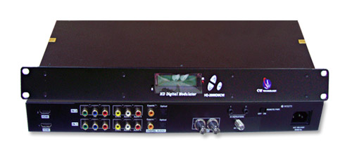
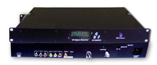
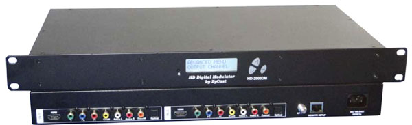
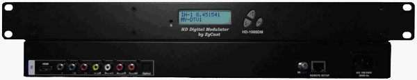
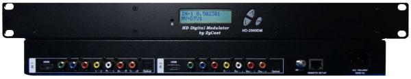
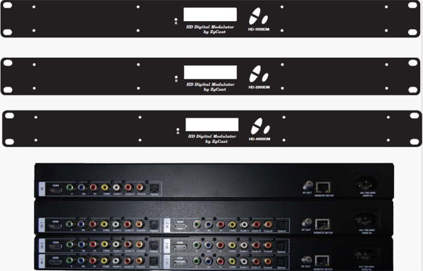
| PRODUCT PICTURES and DIAGRAMS |
| HD‐1000DM |
 |
|
HD‐2000DM |
 |
|
HD‐4000DM |
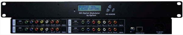 |
|
|
| HARDWARE INSTALLATION and CONNECTION |
 |
|
| 1、 |
The unit is designed to be rack mounted in a standard EIA 19” rack. |
| 2、 |
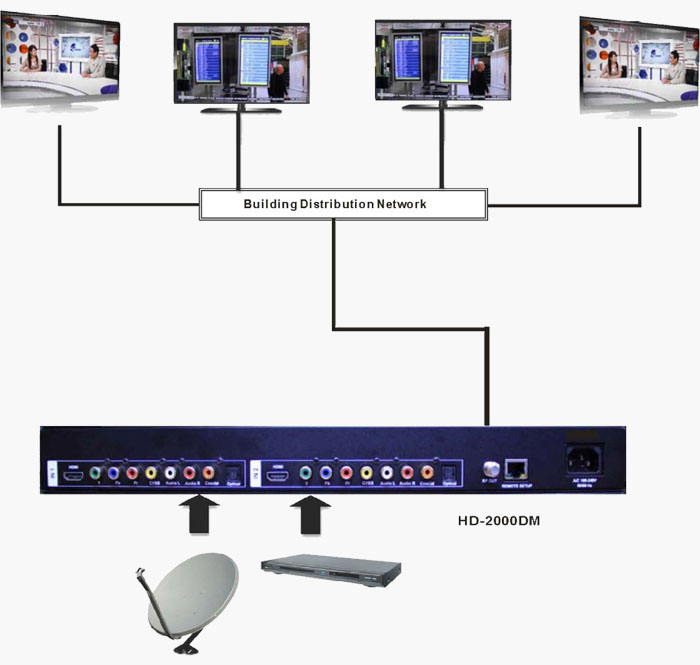
The unit comes standard with HDMI, Component, and Composite video inputs |
| |
The DM encoder / modulators are intelligently designed to detect the active video input from the |
| |
video source. HDMI Connection: Connect the HDMI cable(s) from the video source(s) into the HDMI input(s) on unit. If using a Component Video Cable, connect the Y (Green), Pb (Blue), and Pr (Red) video source cable to the unit’s Component input ports. If using a Composite Video source, use a 75Ω coaxial cable with RCA connectors to connect the video source (e.g., CATV,DVD, VCR, Camera) to the unit’s yellow RCA VIDEO INPUT (CVBS port) jack (IN1…IN2 depending on the DM model). |
| 3、 |
Component / Composite Audio inputs: Connect a Digital Audio Coaxial cable or Optical (Toslink) |
| |
cable for Digital Audio use from the audio source. For A/V audio input (Left / Right Audio) use RCA |
| |
cables to connect the audio source to the red / white AUDIO L and AUDIO R INPUT jacks (IN1…IN2 |
| |
depending on the HD model). Use the red and white jacks for audio input or either one for a single input. |
| |
Repeat this step for each audio source connection. |
| |
Be sure the video and audio connections for each source are consistent with the unit’s inputs (IN1…IN2 depending on the HD model). |
| 4、 |
Use a quality 75Ω coaxial cable with “F” connectors from the unit’s RF OUT jack to the distribution |
| |
system (combiner or reverse splitter) or directly to a television. |
| 5、 |
Connect the included power cord to the unit’s POWER plug. |
| 6、 |
Connect the power cord to an appropriately rated AC power outlet. |
|
 |
MODULATOR SETUP AND CONFIGURATION
NITIAL SETUP TO FACTORY DEFAULT |
 |
| The HD-1000DM/2000DM/4000DM’s front panel is used to configure the modulator as desired. |
|
| MODULATOR CONFIGURATION |
| Once the modulator is powered up it will go through an internal booting process. When “Running” appears in the LCD Display the unit is ready for programming or operation. |
| ※ |
Password – Press the OK button to enter the password 0000. Use the Scroll Up/Down button set the |
|
password. The default password is 0000. Press the OK button for each number to enter the password. |
| |
*** NOTICE TO THE INSTALLER- SEVERAL INTERNAL FUNCTIONS ARE RESERVED OR SET FOR FUTURE USE. SKIP OVER THESE ‘RESERVE’ MENUS WHEN SETTING UP THE ENCODER FOR YOUR APPLICATION. |
| ※ |
Advanced Menu – To access the Advanced Menu first enter the password by pressing the OK button. |
| |
Once the correct password is entered press the OK button and the LCD Screen will display “Advanced |
| |
Menu Output Channel”. The following configuration options are available under Advanced Menu: |
|
| |
● |
Output Channel – Use the Scroll Up/Down button to change the output channel. Once the desired |
| |
output channel is selected press the OK button to set the channel. |
| |
● |
Attenuation – Use the Scroll Up/Down button to select Attenuation. Press the OK button to enter the |
| |
Attenuation menu. Use the Scroll/Up down button to select the desired attenuation in 1dB increments |
| |
from 0 to minus 20 dB. Once the desired attenuation level is found press the OK button to set. (1-10 |
| |
with +/-0.2dB Accuracy). |
| |
● |
Constellation –Use the Scroll Up/Down button to select Constellation. Press the OK button to enter the |
| |
Constellation menu. The modulator is set for QAM64 only. Press the OK button to set. |
| |
● |
FEC – Use the Scroll Up/Down button to select FEC. Press the OK button to enter the FEC menu. Use |
| |
the Scroll Up/Down button to select the desired FEC values then press the OK button to set. Menu |
| |
options are 1/2, 2/3, 3/4, 5/6, 7/8 for HD-1000DM and 7/8 for HD 2000DM/HD-4000DM. The factory |
| |
default is 7/8. |
| |
● |
GUARD INTERVAL – Use the Scroll Up/Down button to select GUARD INTERVAL. Press the OK |
| |
button to enter the GUARD INTERVAL menu. The GUARD INTERVAL is set for 1/32 only. Press the OK |
| |
button to set. |
| |
● |
OFDM MODE –Use the Scroll Up/Down button to select OFDM MODE. Press the OK button to enter |
| |
the OFDM MODE menu. Menu options are 2K, 8K. The factory default is 8K. Use the Scroll Up/Down |
| |
button to select the desired OFDM MODE and press the OK button to set. |
| |
● |
RF Output – Use the Scroll Up/Down button to select RF Output. Press the OK button to enter the RF |
| |
Output menu. Menu options are Normal, Inverted and C.W. The factory default is Normal. Use the Scroll |
| |
Up/Down button to select the desired RF Output and press the OK button to set. |
| |
● |
Brightness – Use the Scroll Up/Down button to select Brightness. Press the OK button to enter the |
| |
Brightness menu. Use the Scroll Up/Down button to select the desired Brightness value (0 to 255) and |
| |
press the OK button to set. Factory default is 128 |
| |
● |
Contrast – Use the Scroll Up/Down button to select Contrast. Press the OK button to enter the |
| |
Contrast menu. Use the Scroll Up/Down button to select the desired Contrast value (0 to 255) and press |
| |
the OK button to set. Factory default is 128. |
| |
● |
Saturation – Use the Scroll Up/Down button to select Saturation. Press the OK button to enter the |
| |
Saturation menu. Use the Scroll Up/Down button to select the desired Saturation value (0 to 255) and |
| |
press the OK button to set. Factory default is 128. |
| |
● |
Hue – Use the Scroll Up/Down button to select Hue. Press the OK button to enter the Hue menu. Use |
| |
the Scroll Up/Down button to select the desired Hue value (0 to 255) and press the OK button to set. |
| |
Factory default is 128. |
| |
● |
Device Address – Use the Scroll Up/Down button to select Device Address. Press the OK button to |
| |
enter the Device Address menu. Use the Scroll Up/Down to select the Desired Address ranging from |
| |
1 to 255 then press the OK button to set. |
| |
Setting the Device address to 0 will clear and reset any Network Parameters (Host Name, Revert to DHCP, IP Address, and MAC address) back to factory default settin All previous settings will be lost if 0 is selected. |
| |
● |
CELL ID –Use the Scroll Up/Down button to select CELL ID. Press the OK button to enter the CELL ID |
| |
menu. Use the Scroll Up/Down button to select the desired CELL ID ranging from 0 to 65535 then press |
| |
the OK button to set. Factory default is 0. |
| |
● |
Stream ID – Use the Scroll Up/Down button to select Stream ID. Press the OK button to enter the |
| |
Stream ID menu. Use the Scroll Up/Down button to select the desired Stream ID ranging from 0 to |
| |
65535 then press the OK button to set. Factory default is 1000. |
| |
● |
Network ID – Use the Scroll Up/Down button to select Network ID. Press the OK button to enter the |
| |
Network ID menu. Use the Scroll Up/Down button to select the desired Network ID ranging from 0 to |
| |
65535 then press the OK button to set. Factory default is 100. |
| |
● |
ORG Network ID – Use the Scroll Up/Down button to select ORG Network ID. Press the OK button to |
| |
enter the ORG Network ID menu. Use the Scroll Up/Down button to select the desired ID ranging from 0 |
| |
to 65535 then press the OK button to set. Factory default is 10. |
| |
● |
Network Name – Use the Scroll Up/Down button to select Network Name. Press the OK button to enter |
| |
the Network Name menu. Use the Scroll Up/Down button to select the first character for the desired |
| |
Network Name then press the OK button to set. Repeat the process for each character in the desired |
| |
Network Name. A Network Name can consist up to 16 characters. |
|
| * Default Configuration – |
|
Caution: Once the OK button is pressed at the Default Config menu the unit will automatically reset to the factory default settings. All settings or changes to the encoder/modulator will be lost. |
|
If you wish to set the modulator back to the factory default settings use the Scroll Up/Down button to reach Default Configuration then press the OK button. |
|
one Audio Input scroll through the Advanced Menu for the additional Audio Input menus.
| |
● |
LCN Mode – Use the Scroll Up/Down button to select LCN Mode. Press the OK button to enter the |
| |
LCN Mode menu. Use the Scroll Up/Down button to select the desired LCN Mode.
|
| |
Options are: APN, EACEM, ITC, NorDig. Factory Default is: APN. Select the desired LCN Mode then |
| |
press the OK button to set. |
| |
● |
1 Video Input – Use the Scroll Up/Down button to change the Video Input Selection. Select:
|
| |
HDMI, Component, Composite, ASI, or Auto. Once the desired Video Input is selected press the OK . |
| |
button to set the Video Input Selection. Factory Default is Auto. If the modulator has more than one |
| |
video input scroll through the Advanced Menu for the additional Video Input menus. |
| |
**ASI input may not be available on your specific model. |
| |
● |
1 Program Num – Use the Scroll Up/Down button to select 1 Program Num. Press the OK button to |
| |
enter the 1 Program Num menu. Use the Scroll Up/Down button to select the desired 1 Program Num |
| |
option ranging from 0 to 65535 then press the OK button to set. Factory default is 1001. If the |
| |
modulator has more than one video input scroll through the Advanced Menu for the additional Program |
| |
Num menus. |
| |
● |
1 Channel Name –Use the Scroll Up/Down button to select the Channel Name. Press the OK button |
| |
to enter the Channel Name menu. Use the Scroll Up/Down menu to select the first character of the |
| |
desired Channel Name then press the OK button to set. Repeat the process until the Channel Name |
| |
is completed. If the modulator has more than one video input scroll through the Advanced Menu for |
| |
additional Channel name menus. |
| |
● |
1 Provider Name – Use the Scroll Up/Down button to select the Provider Name. Press the OK button |
| |
to enter the Provider Name menu. Use the Scroll Up/Down menu to select the first character of the |
| |
desired Provider Name then press the OK button to set. Repeat the process until the Provider Name |
| |
is completed. If the modulator has more than one video input scroll through the Advanced Menu for |
| |
additional Provider Name menus. |
| |
● |
1 LCN – Use the Scroll Up/Down button to select 1 LCN. Press the OK button to enter the 1 LCN |
| |
menu. Use the Scroll Up/Down button to select the desired LCN value then press the OK button to set. |
| |
The 1 LCN value range is from 1 to 999. If the modulator has more than one video input scroll through |
| |
the Advanced Menu for additional LCN menus. |
| |
● |
1 Aspect Ratio – Use the Scroll Up/Down button to select Aspect Ratio. Press the OK button to enter |
| |
the Aspect Ratio menu. Use the Scroll Up/Down button to select the desired Aspect Ratio option of 4:3 |
| |
or 16:9 then press the OK button to set. Factory default is 16:9.If the modulator has more than one |
| |
video input scroll through the Advanced Menu for additional Aspect Ratio menus. |
| |
● |
1 Video Output -Use the Scroll Up/Down button to select Video Output Format. Press the OK button |
| |
to enter the Video Output Format menu. Use the Scroll Up/Down button to select the desired Video |
| |
Output Format: MPEG2 or AVC then press the OK button to set. Factory default is MPEG2. |
| |
● |
1 HDCP - Use the Scroll Up/Down button to select HDCP. Press the OK button to enter the HDCP |
| |
menu. Use the Scroll Up/Down button to select the proper control: Enable or Disable. The Factory |
| |
default is Enable. If the modulator has more than one video input scroll through the Advanced Menu for |
| |
additional HDCP menus. |
| |
● |
1 Audio Input – Use the Scroll Up/Down button to select. Press the OK button to enter the Audio Input |
| |
menu. Use the Scroll Up/Down button to select the Audio Input option: Analog (L/R), Coaxial, Optical, |
| |
HDMI, or Auto. The factory default is Auto. Press the OK button to set. If the modulator has more than |
| |
● |
1 Audio Output – Use the Scroll Up/Down button to select Audio Output. Press the OK button to enter |
| |
the Audio Output menu. Use the Scroll Up/Down button to select the Audio Output option: MPEG2 |
| |
Layer I, AAC, AC-3 Pass Through. The factory default is AC-3 Pass Through. Press the OK button to |
| |
set. If the modulator has more than one Audio output scroll through the Advanced Menu for the |
| |
additional Audio Output menus. |
| |
● |
1 Closed Caption-Use the Scroll Up/Down button to 1 Closed Caption. Press the OK button to enter |
| |
the 1 Closed Caption menu. Enable / Disable 1 Closed Caption control. If the modulator has more |
| |
than one Video Output scroll through the Advanced Menu for the additional Closed Caption menus. |
| |
NOTE: WHEN USING CLOSED CAPTIONING- USER MUST CONNECT FROM THE CONTENT SOURCE THE COMPOSITE OUTPUT OR CC OUTPUT SOURCE TO THE ENCODER'S CVBS INPUT CONNECTOR |
|
| ※ |
To exit the Advanced Menu use the Scroll Up/Down button to select Exit then press the OK button. Exit Exit |
| |
Menu will appear on the LCD screen. Press the OK button twice to exit. |
|
****** IMPORTANT – SAVE THE SETTINGS ****** |
| ※ |
Once the settings are made and the modulator is programmed (a) remove power from the unit by
|
| |
disconnecting the power cable (b) wait 5 seconds and (c) reconnect the power cable to the unit. |
| |
This will allow the modulator to capture the new settings. |
|
Procedure to connect to the Encoder via the remote setup port
The following procedure will allow the installer to setup the Encoder via the GUI |
| (Intranet setup- closed LAN setup) |
|
| 1. Power up the Encoder. |
2. Press the OK button on the Front Panel. |
3. Enter the Password 0000 to enter Advanced Menu Setup. |
4. Scroll to the Device Address Menu. |
 |
5. Set a unique Device address for each encoder being installed in the system.
Device Address ranges from 1~255 |
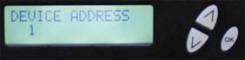 |
| Warning: Setting the “DEVICE ADDRESS” to 0 will clear the network setting to the Factory |
| Default value. |
|
| 6. |
Connect each encoder using a standard CAT5e cable from the Remote Setup port (located on the |
| |
rear panel of the encoder) to a switch. Connect a CAT5e cable from the switch a PC. |
| |
NOTE: To connect to the encoder directly to a PC use a CAT5e Crossover cable |
|
| 7. |
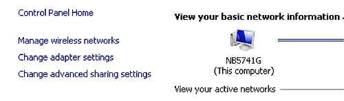
Set the PC via the Control Panel to “Obtain an IP address automatically” |
| |
Start- Control Panel |
| |
View Network Status and Tasks |
| |
 |
|
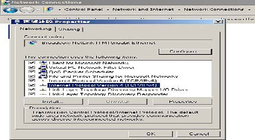
8. Select 'Change Adapter Settings' from the left plane |
 |
|
| 9.Select Local Area Connection Icon |
| Then Right Click – Select Properties |
Internet Protocol Version 4(TCP/IPv4) Properties |
 |
|
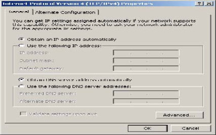
10.Select “Obtain an IP address automatically” & “Obtain DNS server address automatically” |
 |
|
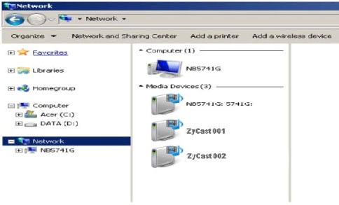
11.
|
After setting the PC to obtain IP address & Obtain DNS server automatically |
| |
Select Start- Computer- Network |
 |
|
12. |
After selecting Network- the encoders will show up on the right side under Media Devices. Each |
| |
device will show up by Device Address. (ZyCast001, 002, 003...) Right Click on the icon for the |
| |
Encoder you want to setup. Select ‘View device webpage’ |
 |
|
13. Welcome page will be displayed as shown |
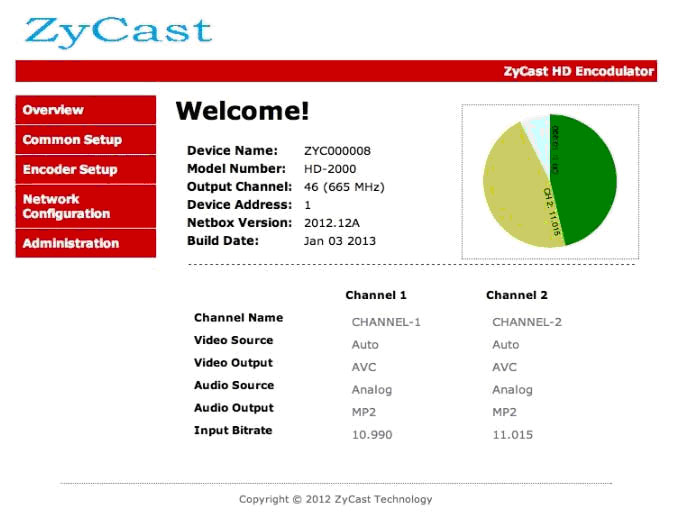 |
|
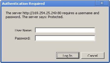
14. Select the Common Setup tab.
|
| |
User will be presented with encoders 'Authentication Required' screen. |
 |
|
| 15. |
Enter User Name and Password.
|
| |
User Name: admin |
| |
Password: Admin123 |
|
| 16. |
Change settings of the encoder via the Common Setup, Encoder Setup, Network Configuration, |
| |
and Administration Tabs. |
|
17. Select Network Configuration Tab. |
| 18. Confirm 'Enable DHCP' check box is selected for closed in-house network. |
(If using internet to connect to the Encoder see Internet setup procedure) |
| 19. |
Save all changes. The user is required to do a local save if any changes are made on the Common |
| |
/ Encoder Setup tabs. Once all changes have been made and are complete- use the Upload and |
| |
Reboot function to apply changes. |
| |
'Waiting for device rebooting' will appear as unit reboots and save the changes. |
| |
After the encoder recovers from rebooting- we recommend you save/ backup the configuration file for each encoder. |
|
| 20. |
Select Administration Tab- then Backup. A config.hex file will be created. The file will be located in |
| |
My Computer->C Directory->Documents and Settings->User-> My Documents -> Downloads > |
| |
configs.hex |
|
|
NOTE TO INTEGRATOR |
WE HIGHLY RECOMMEND YOU RENAME THE CONFIG.HEX FILES FOR EACH ENCODER DEVICE |
| EXAMPLES: config_single_dev1_sitename.hex , config_dual_dev2_sitename.hex |
CONFIGURATION FILES FOR THE SINGLE AND DUAL ENCODERS ARE DIFFERENT AND ARE NOT |
| INTERCHANGEABLE. |
|
Procedure to connect to the Encoder for remote access and monitoring
|
| The following procedure will allow the integrator to access the encoder via the GUI for remote status |
| monitoring and control. |
|
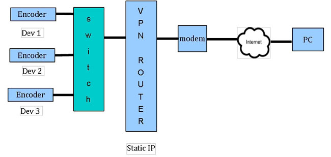
Overview of Setup |
| Accessing the Encoders via the internet will require a VPN device with a Static |
 |
|
1. Using the instructions located in Procedure to connect to the Encoder via the remote setup port enter |
| |
a unique Device Address for each encoder. |
| 2. Setup each encoder's output channel and other parameters as required. |
| 3. Select the Network Configuration Tab. |
| 4. Deselect 'Enable DHCP' |
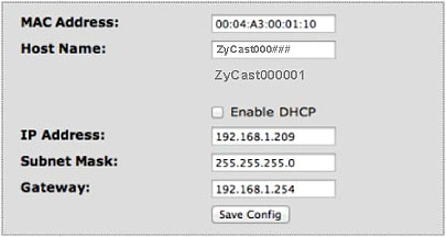 |
| 5. Enter a unique Static IP address for each encoder. |
6. Enter the Subnet Mask. |
| 7. Enter the Gateway IP address from VPN device. |
| 8. Save Configuration of Network settings by selecting Save Config button. |
| 9. Connect the Ethernet switch to the VPN Device (Static IP Required) connected to the internet. |
Contact your network administrator for the VPN device setup |
| 10.Establish a VPN connection from a PC or laptop from an external internet connection. |
11.Once the VPN tunnel has been established-Enter the Specific IP address of the Encoder you which |
| |
to monitor in your internet browser (example: 192.168.100.10) |
12.Save any changes made to the encoder and reboot encoder. |
|
|
HD MODULATOR NOTES |
PRODUCT NOTES: |
ITEM |
VALUE |
PASSWORD |
|
SERIAL NUMBER |
|
INSTALLATION DATE |
|
PURCHASE DATE |
|
VIDEO 1 INPUT |
|
VIDEO 2 INPUT |
|
VIDEO 3 INPUT |
|
VIDEO 4 INPUT |
|
|
|
|
|
|
|
|